- Tel: 0086 13501592453
- Email: sales@consnant.com


What Are You Looking For?

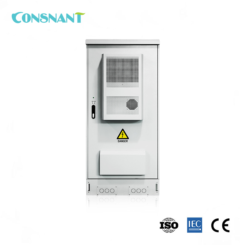
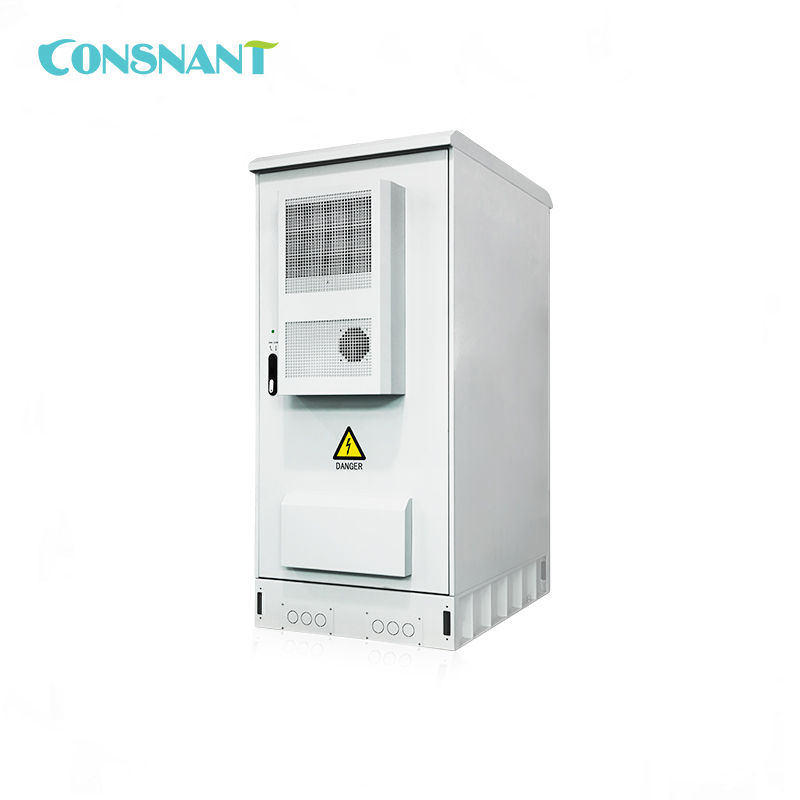
Model Number: CNW330 10-40KVA
Nominal Capacity: 10-40KVA
Nominal Voltage: 208VAC
Maximum Input Voltage Range: ±20%
Nominal Frequency: 50/60HZ
Item No :
CNW330 10-40KVAOrder(MOQ) :
1Payment :
T/TProduct Origin :
ChinaColor :
RAL7035Shipping Port :
ShenzhenLead Time :
3 weeksWeight :
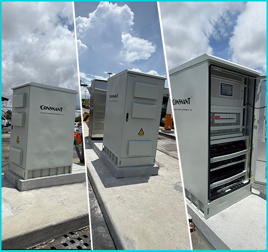
273-602 KgApplication
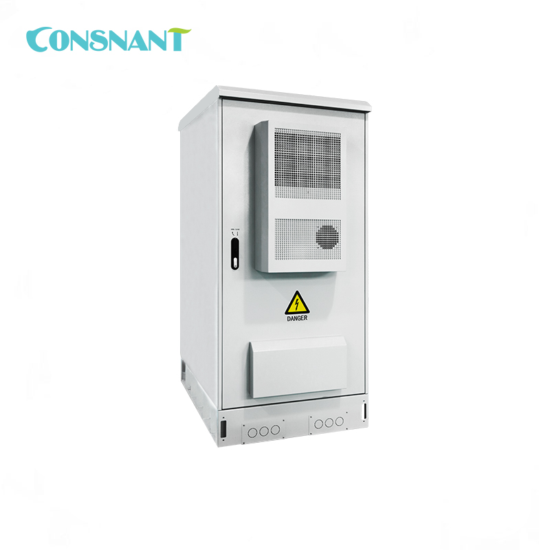
Our outdoor UPS CNW330 series is specially designed for telecommunication base stations.Whether it is used in remote sites or urban networks, our professional team can design solutions for various application scenarios, whether outdoor or indoor, to ensure the smooth operation of power equipment.
System Layout Diagram:

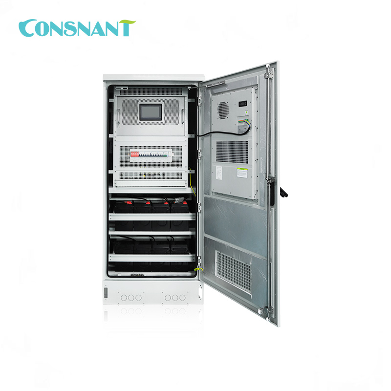
The UPS consists of the following blocks:
RECTIFIER
Converts the input AC power to DC power, The functions are the following:
- Powering the inverter with direct current.
- Charging the battery automatically. Float charge to 80% first, then equalized charge at a constant voltage.
The charging current is limited to 15% of the battery Ah value (stored in memory!) This charging current will only be executed when the total output does not exceed 110% of the rated value.
EXTERNAL BATTERY
Provides the reserved energy for powering the load when there is no power input to the UPS.
HARMONIC REDUCTION FILTER (optional)
The filter, in the front stage of rectifier, reduces harmonic distortion of input current. It consists of two inductors and several capacitors, and is protected by a fuse.
INVERTER
Converts the DC power of a rectifier or battery into AC power. It remains in working condition at all times to provide power to the load.
STATIC SWITCH
Allows to automatically or manually switch between INVERTER output and BY-PASS bypass output in real-time.
At the same time, this static switch has a "Backfeed Protection" device to prevent current feedback caused by abnormal SCR faults.
SWMB
Turn on the SWMB switch and turn off other switches SWIN, SWBY, or SWOUT, the UPS will be isolated for maintenance purposes. At this point, the load can still obtain power without being affected, because there is no voltage inside the UPS (The voltage only exists in the input/output terminal block and switch section. But on UPS with three-phase output, the neutral line is not separated!).
Technical Parameters
|
Model |
CNW330-10K |
CNW330-15K |
CNW330-20K |
CNW330-30K |
CNW330-40KVA |
|
Capacity |
10KVA |
15KVA |
20KVA |
30KVA |
40KVA |
|
System parameters |
|||||
|
Relationship between output power factor cosφ and the load |
|||||
|
0.5~0.8 inductive load |
100% |
||||
|
0.8~1.0 inductive load |
100~80% |
||||
|
1.0 linear Load |
80% |
||||
|
0.8~1.0 capacitive load |
80% |
||||
|
0.5~0.8 capacitive load |
70% |
||||
|
Computer load |
80% |
||||
|
Overall efficiency (normal mode) Load 100% |
92% |
||||
|
50% load |
90% |
||||
|
Overall efficiency (economic model): 100% load |
98% |
||||
|
Max leakage current(mA) |
100 |
||||
|
Standby economy mode |
Standard function |
||||
|
Mean time between failures(MTBF): |
200,000 hours |
||||
|
Computer monitoring port |
Standard configuration RS232, RS485 / MODBUS |
||||
|
Operating temperature |
-10° ~ 50 °C |
||||
|
Max relative humidity |
95 % (non-condensing) |
||||
|
Cooling |
Forced ventilation (fan speed varies with load and temperature) |
||||
|
Maximum altitude |
Rated power at 1000m (increase by 100m and decrease by -1%), maximum 4000m |
||||
|
Noise (dB) |
52 ~ 58 |
||||
|
Protection class(EN 60529) |
IP55 |
||||
|
Incoming and outgoing line method |
Bottom/Back |
||||
|
Safety standard |
\Safety regulations:GB4943 ,EN 50091-1;EMC:GB7260.2,GB/T 17626.2~5EMC, EN 50091-2 |
||||
|
Physical parameters |
|||||
|
Width (mm) W |
900 |
1060 |
|||
|
Depth * Height (mm) |
1200*1950 |
1295*1950 |
|||
|
Weight ( Kg)(Battery not included) |
273 |
299 |
311 |
454 |
602 |
|
Rectifier input |
|||||
|
Rated voltage |
208VAC Three phase three wire |
||||
|
Voltage range |
± 10 % (± 20 % adjustable) |
||||
|
Rated frequency |
50/60Hz Automatic identification |
||||
|
Frequency range |
45 ~ 65 |
||||
|
Input power soft start function |
Yes, 0-100%,10-300 seconds settable |
||||
|
Input power factor cosφ |
Up to 0.99 (with harmonic filter) |
||||
|
Input current harmonic component(THDI ) |
Minimum<5% (with harmonic filter) |
||||
|
Max. input current [A] |
33 |
49 |
66 |
99 |
133 |
|
Rectifier output |
|||||
|
Maintenance voltage (20°C) |
Battery type1 and 2 :V = (2.266 * el.) Vdc |
||||
|
Battery type 3 :V = (2.21 * el.) Vdc |
|||||
|
Battery type 0:The voltage value is between type 1 and 2, and the voltage value adjustment range V =(2.09~2.4) * el. [Vdc] |
|||||
|
Charging Voltage (20°C) |
Battery type1 and 2 :V(%Recharging<95%)= (2.32 * el.) Vdc |
||||
|
Battery type 3 :V(%Recharging<95%)= (2.4 * el.) Vdc |
|||||
|
Battery type 0:The voltage value is between type 1 and 2, and the voltage value adjustment range V =(2.09~2.4) * el. [Vdc] |
|||||
|
Max charging Voltage |
(2.32 * el.) Vdc |
||||
|
Charger output voltage stabilization accuracy |
1% |
||||
|
DC ripple voltage component |
≤1% |
||||
|
Battery |
|||||
|
Number of units (rated voltage) |
16 units(192VDC) |
||||
|
Charging current setting |
0.1A x C10 |
||||
|
Battery discharge termination voltage |
Battery 1, 2 and 3:No-load discharge current,Vmin=(1.81 * el.) [Vdc] |
||||
|
Battery 1, 2 and 3:output current=Ah Capacity,Vmin=(1.65 * el.) [Vdc] |
|||||
|
Battery 1, 2 and 3:output current>Ah Capacity,Vmin=(1.60 * el.) [Vdc] |
|||||
|
Battery 0 type: Factory default values ,Vmin=(1.67 * el.) [Vdc] Adjustment range Vmin =(1.57~1.88)*el. [Vdc] |
|||||
|
Three-phase inverter output |
|||||
|
Rated capacity [KVA] |
10 |
15 |
20 |
30 |
40 |
|
Rated power[KW] |
8 |
12 |
16 |
24 |
32 |
|
Rated voltage [V] |
208VAC Three-phase four-wire |
||||
|
Rated current [A] |
22 |
33 |
44 |
66 |
88 |
|
Phase voltage setting |
112~ 135 V (control panel ) |
||||
|
Peak factor(Ipeak/Irms) |
3:1 |
||||
|
Wave form |
Sine wave |
||||
|
Voltage phase shift (degrees) 100% balanced load |
± 1' |
||||
|
Voltage phase shift (degrees) 100% unbalanced load |
± 2' |
||||
|
Phase voltage difference 100% balanced load |
± 1 % |
||||
|
Phase voltage difference 100% unbalanced load |
± 3 % |
||||
|
Total harmonic content(THDv) 100%linear Load |
<2% |
||||
|
Total harmonic content(THDv) 100% non-linear Load |
<5% |
||||
|
Steady voltage stability |
± 1 % |
||||
|
Transient voltage response |
± 5 % within 10ms |
||||
|
Rated frequency |
same as input |
||||
|
Frequency stability |
± 0.5% when asynchronous; During synchronization, ± 2% (can be set to ± 1-5%, operated by the panel) |
||||
|
Overload |
600’ / 10’ / 1’ (110/125/150% Rated current) |
||||
|
Short circuit for 0.1 seconds |
2 times input |
||||
|
Inverter efficiency(100% load) |
90% |
||||
|
Three phase bypass input |
|||||
|
Rated capacity [KVA] |
10 |
15 |
20 |
30 |
40 |
|
Rated voltage [V] |
208VAC Three-phase four-wire |
||||
|
Input voltage range |
±15 %(Can be adjusted from the control panel to± 10 %,± 20%) |
||||
|
Rated frequency [Hz] |
50 / 60 |
||||
|
Voltage range |
±2 %(Can be adjusted from the control panel to± 5 %) |
||||
|
“STAND-BY ON” (Switching time from bypass to inverter in economic mode) |
2~5ms |
||||
|
Inverter/bypass switchover time |
<1ms |
||||
|
Overload capacity |
10’/1’/18”(150/175/200% Rated current) |
||||
|
Standard configuration |
Feed current protection |
||||
Tags :
 Sign Up To Our Newsletters
Tel : 0086 13501592453
Email : sales@consnant.com
Address : Building B6, Junfeng Industrial Park, Yonghe Road, Fuhai Sub-District, Bao'an District, Shenzhen City, 518103, P.R.China
Copyright © 2026 Shenzhen CONSNANT Technology Co., Ltd. All Rights Reserved
 IPv6 network supported